This board is not breadboard friendly often separate programming module is used for programming. Wemos DMini Pinout. The following figure shows the WeMos DMini pinout.
We compare the specifications of the different microcontroller and take a look at the pinout in detail. V source it will get damaged. GND:-ve pin, connect it to the. On the bottom of this blog you can download the PDF!
GND: -ve pin, connect it to the ground of your circuit. HIGH to allow the module to boot up. Notable difference between and pins variants is that pins has LEDs outside shield. Also, antenna socket is on the bottom left, whereas 14-pin has antenna on the top left.

Please help me to solve my problem. Zu diesem Zweck wird dieser Pin beim Einschalten der Spannungsversorgung oder während eines Resets mit GND verbunden. Danach kann die Verbindung zu GND gelöst werden.
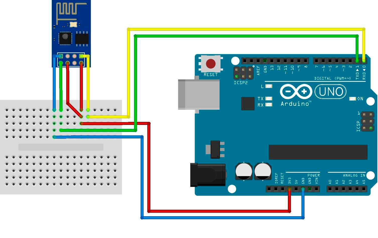
Additionally, the Wi-Fi module has a reset pin, as well as CH_P to reboot. Step 1: The ESP-in a Nutshell. The “standard” version has digital pins that can be used for input or output. It supports the 802. I have seen the ESP-pinout and found GPIOand GPIO.
Pin Definitions Figure 2-shows the pin layout for 32-pin QFN package. Pin Layout (Top View) Table 2-lists the definitions and functions of each pin. In this tutorial, we will make it easy for you to understand the initial step so you can do it your self.
_211241_2_Normal_Large.jpg)


