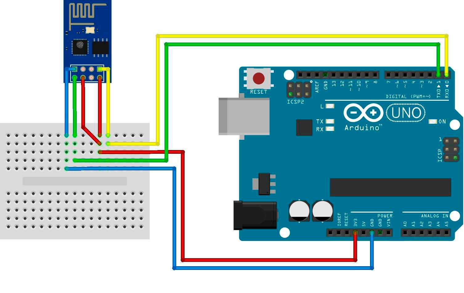
This board is not breadboard friendly often separate programming module is used for programming. Wemos DMini Pinout. The following figure shows the WeMos DMini pinout.
We compare the specifications of the different microcontroller and take a look at the pinout in detail. V source it will get damaged. GND:-ve pin, connect it to the. On the bottom of this blog you can download the PDF!
GND: -ve pin, connect it to the ground of your circuit. HIGH to allow the module to boot up. Notable difference between and pins variants is that pins has LEDs outside shield. Also, antenna socket is on the bottom left, whereas 14-pin has antenna on the top left.

Please help me to solve my problem. Zu diesem Zweck wird dieser Pin beim Einschalten der Spannungsversorgung oder während eines Resets mit GND verbunden. Danach kann die Verbindung zu GND gelöst werden.
Additionally, the Wi-Fi module has a reset pin, as well as CH_P to reboot. Step 1: The ESP-in a Nutshell. The “standard” version has digital pins that can be used for input or output. It supports the 802. I have seen the ESP-pinout and found GPIOand GPIO.
Pin Definitions Figure 2-shows the pin layout for 32-pin QFN package. Pin Layout (Top View) Table 2-lists the definitions and functions of each pin. In this tutorial, we will make it easy for you to understand the initial step so you can do it your self. Programming ESP is a bit hard for beginners.
We’ll show you the pinout for those boards. If you’re using another development boar make sure you have the right pinout. ESP-12E NodeMCU Kit Pinout. A jumper allows selection of 3Vor 5Vas input voltage coming in via the FTDI cable.
Ask Question Asked years, months ago. LED Blinking hello world programming for ESP WiFi Module. Active months ago. This is not a complete list of available modules but a selection of the ones I could test and review. In the first mode, you set the WiFi module to act as a Station (STA).
The module gains the ability to connect to an available WiFi network. In the second mode, you set the WiFi module to act as an Access Point (AP). Now I was ready to go.
Ich habe zwar geschafft, irgendwelche Sketche auf den esp zu laden, jedoch bekomme ich nach dem xxx weder ein Blinken, noch sonst etas zum Laufen. Lasse ich GPIOnach dem Reset unverbunden, schaltet der esp sich aus. The hardware presented here will allow the ESP- to boot up in program mode and normal mode.
The slide switch (S1) allows easy switching between program and normal modes, while the tactile switch (S2) can be used to reset the ESP- (after each mode selection, the reset button can be pressed to enter that state). V (source current). This breakout offers clear pinout silkprint on top and will nicely fit your prefered breadboard Onboard 0. F decoupling capacitor makes the espesp01s wifi module always run smoothly without a hitch. What you will get is: X ESP-01S adapter board. The IP has to have the same three first numbers with your router IP.
For example if your router IP is 192. Installation instructions, functions and classes reference.


Inga kommentarer:
Skicka en kommentar
Obs! Endast bloggmedlemmar kan kommentera.