How PNP Transistors Work. When I say “turn on”, I mean that the transistor will open up a channel between emitter and collector. What is the gain of your PNP? Thus with an emitter voltage of 12V, and the most the Arduino can output is 5V, the transistor will never be off.

A voltage GREATER THAN THE POWER RAIL on the base causes a small current to flow through the base-emitter junction and that allows a larger current to flow from the power source to the load. NPN transistor will be fine. You need a PNP Transistor. However, the problem with this approach is that you are switching the ground (GND) path. Arduino är ett mikrokontrollerkort som är öppen hårdvara.
Hårdvaran består av en enkel och öppen kretsdesign med en Atmel AVR och stöd för in- och utgångar. So it will turn on. The problem comes when you want to turn it off. V (9V - V), and that is impossible for an Arduino to do. This post addresses all three issues regarding how to PWM a 3-pin PC fan with an Arduino.
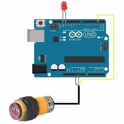
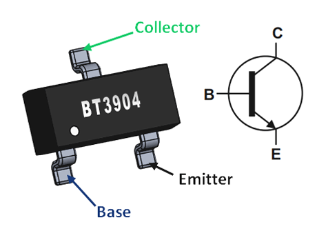
The only difference is the direction of the arrow on the emitter. In a NPN (on the left) it points outwar for a PNP (on the right) it points inward. Wiring Guide with Arduino MCU The metal proximity sensor will have three color wire. These are used in the amplifying circuits. Used in Darlington pair circuits.
Schematic view of a potentiometer and transistor connected to an Arduino. PNP transistors are used to source current, i. The third leg is connected to ground. The base of the transistor is connected to digital pin of the Arduino through a 1-kilohm resistor.
Open the arduino -1. Right click on it and choose Run in Terminal from the contextual menu. The installation process will quickly end and you should find a new icon on your desktop.
Comparing data collection between a PNP and NPN proximity sensors using an Arduino compatible Teensy. Improve this question. Siddhartha Sadhukhan. For a PNP BJT, the base and the collector are associated with a negative voltage input, therefore naturally the emitter of a PNP must be referenced to the positive line, so that the positive supply can enter through the emitter and finish its journey from the base and the collector pins. PNP is also known as “Sourcing.

PNP devices switch the positive side of the circuit. NPN devices are known as “Sinking” and can switch the negative side. An NPN device “sinks” or provides -V to the input card when active. For that reason you must use a transistor.
Transistors have limits and maximum specs, just be sure those values are enough for your use. First lets eliminate what is correct and not contributing to the problem. Este es el paso introductorio para la aplicación de un Transistor PnP para ser usado con Arduino. Many of the ardumotor boards do not come with the logic-V set to 5V. If it is not selected to 5V because the leonardo uses 5V logic, the LED sequence will not be correct and the stepper will just make a noise and not move when using slow or fast speeds.

Labor Day bbq this afternoon, taking the family on a harbor cruise tomorrow morning, but Tuesday afternoon or most of the day Wednesday Ill be home (working on my flip-roof observatory!). Give me a call or text and Ill come down the hill, or. If we tried to connect the motor straight to an Arduino pin, there is a good chance that it could damage the Arduino.


Inga kommentarer:
Skicka en kommentar
Obs! Endast bloggmedlemmar kan kommentera.