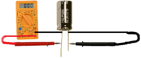
A capacitor is a device that stores electrical energy in an electric field. It is a passive electronic component with two terminals. The effect of a capacitor is known as capacitance. While some capacitance exists between any two electrical conductors in proximity in a circuit, a capacitor is a component designed to add capacitance to a circuit.

The amount of charge it can store in its plate is determined by its Capacitance value. An when the charging current voltage of a capacitor is equal to the supply voltage it’s said to fully charged condition. Here, in this condition the capacitor works as an energy source as long as voltage is applied. The closer the two conductors are and the larger their surface area, the greater its capacitance. In the capacitor three-point oscillating circuit , the capacitor connected in series with the inductor oscillating coil plays a role in eliminating the influence of the transistor junction capacitance on the frequency stability.
I show these ideas conceptually on paper then demonstrate how capacitors beha. What is the time constant for ? In the series circuit above the right hand plate of the first capacitor, C is connected to the left hand plate of the second capac itor, C whose right hand plate is connected to the left hand plate of the third capac itor, C 3. Well, it’s just finding the charge and voltage across each capacitor in a circuit. There are some simple formulas and rules that would allow us to solve two different types of capacitor circuits: series circuit and parallel circuit.
It is also known as a condenser and the SI unit of its capacitance measure is Farad “F”, where Farad is a large unit of capacitance, so they are using microfarads (µF) or nanofarads (nF) nowadays. Step Identify the circuit. A series circuit has only one loop with no branching paths. Given the voltage and capacitor values for each, find the total capacitance.
The two metal plates on the top and bottom of a cap are connected by two electrical terminals that connect it to the rest of a circuit. One end of the capacitor connects to power, and the other flows to ground. Capacitors in the circuit are arranged in order within the same loop. The internal anatomy of a capacitor, we’ve got our two metal plates, the inner dielectric, and connecting terminals. And when it is disconnected from its charging circuit , it can dissipate that stored energy, so it can be used like a temporary battery.

CAPACITIVE AC CIRCUITS A purely capacitive AC circuit is one containing an AC voltage supply and a capacitor such as that shown in Figure 2. As the supply voltage increases and decreases, the capacitor charges and discharges with respect to this change. The capacitor is connected directly across the AC supply voltage. The plates accumulate electric charge when connected to power source. Capacitor is an electronic component that stores electric charge. One plate accumulates positive charge and the other plate accumulates negative charge.
When a series RC circuit is applied across a fixed DC voltage, the capacitor begins charging. It begins charging from volts an at that instant, the current that charges the capacitor is defined by the DC voltage and the value of the series resistor. As the plates discharge during the change of direction, the capacitor output current alternates in phase with the AC voltage.
The vertical wire drawn next to the vertical capacitor shorts the two terminals of the capacitor. This is how capacitors are said to pass AC. Any current flowing through this circuit segment will flow through the vertical wire and completely bypass the vertical capacitor due to the short. The term dielectric is just a fancy word for an insulator that can be polarize i. When voltage is applied across these two plates, current flows through the conductive plates. This circuit contains both series and parallel connections of capacitors.
See Example for the calculation of the overall capacitance of the circuit. The Zener diode is there to prevent overvoltage on the SuperCap foremost. The smaller capacitor takes in the voltagespike at the start of recharging the circuit.
The regular diode is there to limit the direction of flow.


Inga kommentarer:
Skicka en kommentar
Obs! Endast bloggmedlemmar kan kommentera.