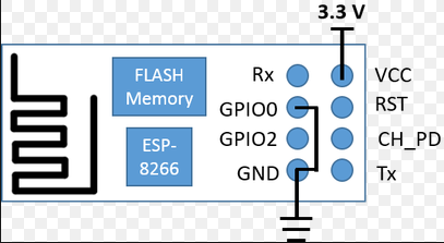
Micro USB, USB to UART bridge and some other components. Note: not all GPIOs are accessible in all development boards, but each specific GPIO works in the same way regardless of the development board you’re using. V (V Max) Power Supply Pin GND Ground Pin Tx Data Transmit Pin (Works at V) Rx Data Receive Pin (Works at V) CH_PD Chip Power Down Pin. Se hela listan på iotbytes. Coverage on all electronic components with their pinout details, uses, applications and pdf datasheets and their Founders.

Personally, I really like this component, as it already comes with USB input. For our mechatronics projects we are mainly interested in the following pins: Power pins ( V). Amica (the company that created both V and V) made this board narrower to fit a breadboard.
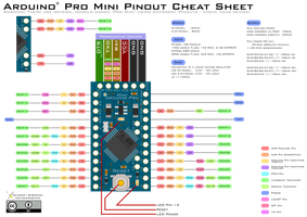
As shown, it has the same pinout structure with V1. Unfortunately, different boards have different pin layouts or configurations. At first glance, once you configure it for programming all the pins are used.
Die GPIO-Pins können jeweils binäre Zustände lesen und ausgeben, also beispielsweise ein Relais ein- oder ausschalten, während die seriellen Pins Tx und Rx nur Daten senden ( T ransmit) bzw. UY The ESPhas pins and the ESP12F has 22. For those that starting with the ESP modules, I have made some pinout diagrams, their functions and how to use them. However only of these GPIO pins can be used for digital input and output operations. These are listed on the table bellow.
To pytanie zadaje sobie wielu elektroników. It may be used either to read voltage at ADC pin, or to read module supply voltage (VCC). To read external voltage applied to ADC pin, use analogRead(A0). Input voltage range is — 1. To read VCC voltage, ADC pin must be kept unconnected.

Documentation () for Tasmota. Date Version Release Notes. Table of Contents 1. Operating voltage and current consumption information of the module is included below.
V, however some many boards may implement voltage dividers. To upload the device Arduino requires the UART communication pins RX and TX only. During the use of ESP12E, there won’t be any library. NodeMCU VPinout NodeMCU Vcomes with a number of GPIO Pins. Following figure shows the Pinout of the board.

Pin Definitions Figure 2-shows the pin layout for 32-pin QFN package. Ask Question Asked years, months ago. Active year, month ago. Viewed 8k times -1. Interrupt Flow Chart.
An Arduino Due is ideal for testing the module. This is because a Due can supply enough current from its 3. V pin and works with 3. But this board is slightly larger than the V1. See Adafruit Huzzah and WeMos DMini. This NodeMCU Pinout article is for reference only.
It runs at 3V with maximum voltage range around 3. This module stays ahead of its predecessor in terms of processing speed and storage capability.

Inga kommentarer:
Skicka en kommentar
Obs! Endast bloggmedlemmar kan kommentera.